A couple of blog postings ago I promised you, my readers, details on Ganymede’s new plumbing setup. This will probably be of supreme disinterest to those who have not lived the joys of marine plumbing and can therefore not sympathise or better yet, smugly nod and say: “better you than me, fool.” But maybe some will watch with interest to see whether it winds up actually working. Which is, of course, my sincerest hope right now.

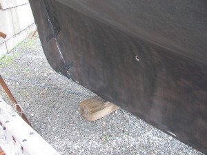
Having a horror of traditional bronze through-hull fittings, with seacocks and hose clamps under the waterline (!!!!????), I had determined, ages ago, never to imperil my boat by putting obvious weak spots where such things ought not to be. Other than no through-hulls at all, which is the ideal, there’s only one other choice: solid tubes glassed firmly to the hull and rising above the waterline before getting a seacock on. For this I found some suitable pultruded fiberglass tubing at McMaster-Carr, and after drilling the necessary holes in the hull with hole saws, proceeded to fit the pipes.
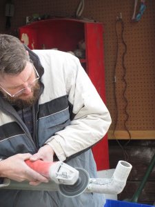
Each pipe needed to be cut at an angle and have a piece spliced on to match the angle of the hole in the hull, the idea being that both pipes (intake and outlet) would rise parallell to each other and the bulkhead to which they’re attached. It took several cuts to get the angle just right, and several trips out to the boat to dry-fit.
Once happy with the angle of each joint, I glued them with thickened epoxy, then overlaid the joint with carbon fiber cloth. Why carbon fiber? Well, because I had it lying around, in bits perfectly suitable for such joints. While I was at it, I made mounting brackets to attach the standpipes to the bulkhead. For these I used some scraps of tubing for a form, and some 1708 fiberglass cloth I had lying around as well.
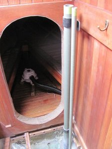
Next step was to fix the pipes to the hull. The astute reader will notice that one hole is on one side of the hull, and the other is across the bilge space from it. This was strategic, since the last thing I wanted was the water intake being next to the outlet. Now there’s an entire full keel separating the two holes, which should keep the water intake as clean as possible. One pipe, then, has to cross the entire bilge space, which will make re-installation of the bilge pump very interesting when I get around to it at last.
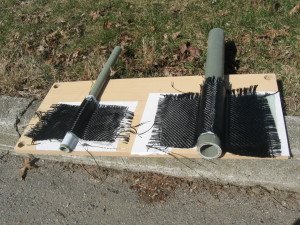
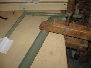
But moving on…the outlet pipe was the first one to be attached, again with carbon fiber, since I didn’t have any suitable fiberglass. After making a fillet with the same thickened epoxy I used to glue the pipe to the hole in the hull, I started wrapping layers of biaxial carbon around the joint. The biax really takes the corners nicely, and I used successively bigger layers to get good overlap on the joint. My brackets, lag-bolted firmly to the bulkhead, held the pipe steady while I worked.

It’s surprising how fast a project can go after all the setting up is done; in no time the outlet was epoxied on and it was time to fit the inlet. This was no different, except that I had to glass the end opposite the hole onto the hull as well. Again this was soon done, an extra strut glued in to keep the pipe from accidental breakage, and I could walk away and let everything dry.

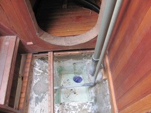
It took a few weeks to find the time and motivation to get out there and hook up all the hoses, valves, anti-siphons, etc., and I might have put it off until after Ganymede was on her mooring, except that I needed the electricity at the boatyard to operate a heat gun. While some of the hose barbs took the hose quite easily, others required some heat-softening and soap lubrication to get the hose on. What I did have to put off until later was painting the bilge afterwards. That I did after moving the boat back to her summer home in the Kickamuit River. I’m afraid it still looks a fright, but at least now it’s a fright of the same color.

I’m not entirely pleased with the jumble of pipes, valves, and hoses that now invades Ganymede’s once simple, convenient head. On the next boat I’ll design the plumbing to be more out-of-sight and elegant. But for now Ganymede is the boat we have, and though we’re sacrificing looks for convenience, she’s continuing to adapt to our needs, and we’re looking forward to a great summer of sailing.